
3. Components of the new energy plant
3.1 Solar power system
|
|
|
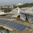
Solar power system is appreciated for environmentally friendly and clean energy source. It is in popular for supplement power source of each home, installed on the roof top of houses. Weather changing every hour, cloudy or sunshiny, influences the power so much, and there is no power in the night. For stabilizing the power, rechargeable battery is required. A NaS rechargeable battery will be introduced as an energy buffer in the exposition. Three types of solar panels, polycrystalline Silicon type (200KW), amorphous Silicon type (100KW) and bi-side type (30KW), will be demonstrated in the exposition (Fig. 5 and 6).
3.2 Sodium Sulfur (NaS) battery system for energy storage
NaS battery is a high energy and a high temperature battery working at 350°C. A special ceramics of beta-alumina is used as a solid electrolyte. Sodium ions pass through the solid electrolyte existing between melting anode (S, Sulfur) and melting cathode (Na, Sodium) for charging and discharging electricity. Self-discharge of the battery is very low because of the solid electrolyte. In the exposition, a NaS battery with 500KW of power and 4MWh of energy is installed for the energy buffer of the solar panels and fuel cells. The battery also acts as an energy buffer of load leveling between night time and daytime.
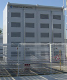
Fig. 7. NaS battery in the exposition area.
3.3 Fuel cells
Fuel cell is not a battery but an electric power generator. Principle of the power generation is based on a chemical reaction between Hydrogen fuel gas and Oxygen gas. This reaction is just reverse chemical reaction of water-electrolysis. Gases exhausted from fuel cells are high temperature water vapor and Carbon di-oxide gas as a result of the chemical reaction. Fuel cells are characterized by high energy-efficiency, low emission to environment, and low noise. So, fuel cells are expected to be widely used in future society.
Table 2 shows several kinds of fuel cells with various electrolytes and working temperatures. Polymer electrolyte fuel cell (PEFC) working at about 90°C is not introduced to the new energy plant, because output power is still now very small (about 1KW). But, automobile companies are trying to improve this power for fuel cell cars.
Two molten carbonate fuel cells (250KW MCFC and 250KW MCFC with micro gas-turbine) are introduced to the new energy plant. MCFC has high energy efficiency because it works at 650°C. High temperature exhaust gas can be re-used for energy source of air conditioning. Methane gas coming from the methane fermentation system is fed to one 250KW MCFC. Hydrogen and Carbon mono-oxide gas coming from the high temperature gasifying furnace is fed to another 250KW MCFC with micro gas-turbine.
Four phosphoric acid fuel cells (PAFC, total 800KW) working at 200°C, and a solid oxide fuel cell (SOFC, 50KW) working at 1000°C, are also introduced to the plant. High temperature exhaust gas coming from the PAFC and the SOFC is also re-used for air conditioning. MCFC, PAFC and SOFC demonstrated in the exposition are shown in Fig. 8, 9 and 10, respectively.
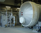
Fig. 8. MCFC.
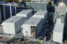
Fig. 9. PAFC.
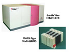
Fig. 10. SOFC.
Table 2. Type of fuel cell.
| High Temperature Type | Low Temperature Type | ||||
| Molten Carbonate Fuel Cell(MCFC) | Solid Oxide Fuel Cell(SOFC) | Phosphoric Acid Fuel Cell(PAFC) | Polymer Electrolyte Fuel Cell(PEFC) | Alkaline Fuel Cell(AFC) | |
| Electrolyte | Carbonate | Ceramiscs | Phosphate | Polymer Film | KOH |
| Charge Carrier | CO32- | O2- | H+ | H+ | OH- |
| Catalyst | no | no | Pt | Pt | Ni, Ag |
| Working Temperature | 650°C | 1000°C | 150 - 200°C | 80 - 100°C | 50 - 100°C |
| Efficiency | 50 - 65% | 55 - 70% | 35 - 42% | 35 - 40% | 60% |
| Feature | High Efficiency Large Capacity |
High Efficiency | Practical Use | Low Temp. High Power |
Low Temp |
| Fuel | Waste Gas Coal Gas Natural Gas LPG Methanol |
Waste Gas Coal Gas Natural Gas LPG Methanol |
Natural Gas LPG Methanol |
Natural Gas LPG Methanol |
Hydrogen |
| Application | Large Scale Generation | Large Scale Generation | Small Scale Generation | Home use EV Use |
Space Ship Millitary |
3.4 Methane fermentation system
Methane fermentation is based on a bio-technology using bacteria. A lot of food garbage estimated 4.8 ton/day will come from restaurants every day. The garbage is collected in the night, and is fed to the methane fermentation system to obtain methane fuel gas for the 250KW MCFC. It takes several weeks to obtain the gas by fermentation. When the methane gas is short, instead, city gas will be fed to the MCFC. Solid residuals from the fermentation system are re-used for compost of trees.
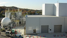
Fig. 11. Methane fermentation system.
In Japan, there are many incinerator plants in cities to burn wet food garbage gathered from each home. Small plants dealing such garbage less than 200 tons/day do not generate electricity, and petroleum must be wasted for burning wet garbage with water. This means that big amount of petroleum is wasted, and also that big air pollution occurs. So, if we introduce methane fermentation system to such small plants in combination with fuel cells, we can deal garbage, we can obtain compost, we can obtain electricity, we can save petroleum, and we can save air pollution, at once.
3.5 High temperature gasifying system
One of the purposes of the exposition is to show ecology in our future society. Some natural trees had to be cut when the exposition area was developed. These trees are ground to fine powder with a mill, and the powder are fed into the high temperature gasifying furnace to obtain fuel gas (Hydrogen and Carbon mono-oxide) for the 250KW MCFC with micro gas-turbine. Plastic bottles collected in the area are also ground to fine powder, and then, powder is fed into the furnace. When the fuel gas is short, instead, city gas is fed to the MCFC. The gasifying system and the photographic view are shown in Fig. 12 and 13, respectively.

Fig. 12. High temperature gasifying furnace.
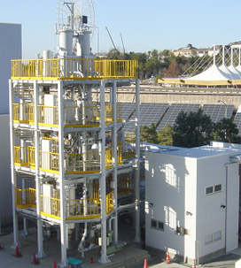
Fig. 13. Photo of the high temperature gasifying furnace.
3.6 Demand and supply controlling computer system
In the new energy system demonstrated in the exposition, power lines coming from the three solar panels (330KW), the two MCFCs (500KW), the four PAFCs (800KW), the SOFC (50KW) and the NaS battery (500KW) are connected together at 6.6KV to supply total 2180KW. Power, about 1200KW, required for the Japan pavilion in Fig.2, is supplied from the new energy system.
Daily power demand of the Japan pavilion is expected to vary like a curve shown in Fig. 14. The PAFCs, the MCFCs and the SOFC are responsible to base load of the demand. The NaS battery is responsible to a special load changing rapidly in the demand, and is also responsible to charging excess power of the fuel cells and the solar panels.
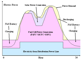
Fig. 14. Daily control of electricity demand and supply.
Energy and power balance between the demand of the Japan pavilion and the supply from the new energy system are controlled by a central computer installed in the plant. Power supplied from the distribution power line is suppressed minimum by the computer. The new energy system will be discussed from the view point of electricity quality, energy cost, reduction of Carbon di-oxide gas, and energy efficiency.